The main brain of the robot is an Atmega32u4 microcontroller. This is mounted on a Spark+ Board created by the QUT Electrical Engineering Society, QUT EES. This board provides the microcontroller with voltage regulation, polarity protection, a motor controller and 28 pin headers for rapid prototyping. The chipset features PWM controllers, needed for controlling the motors, analogue to digital converter, ADC, pins, allowing the analogue value of the sensors to be read, as well as timers and a variety of digital I/O pins.
Break Out Board (BOB)
Data input and output was made possible by connecting the central processing unit of the robot to a Break out board, BOB, which interfaces directly with the sensors, motors and battery. This board provides an interface for feedback, through two LED’s and human input post code compilation through a button, which can be used to toggle different features of the device.
For greater speed performance and to improve the modularity of the system it was decided to run each of the motors directly off the batteries voltage, instead of the 5v of the Spark+ board. Although the Spark+ has a motor driver a diode array was still required to control the motors pull of current from the battery. The BOB was also responsible for providing reverse polarity and voltage protection for the lithium ion battery by using diodes and fuses. The motor diodes used were based on the maximum current draw of the motors at stall, 0.36 A (Pololu, 2018). 1A, low voltage drop diodes were chosen to ensure that this could be provided, a diode of the same type was also used to provide reverse polarity protection for the battery as it had a breakdown voltage of 40V. A 2.5A fast acting fuse was also added to ensure that all components could run optimally but also be protected in the case of a fault.
The decision to incorporate only two LED’s was made to ensure that there was a compromise between board size and the ability to give feedback for both debugging and the end user. The two required states which had to be indicated via visual or auditory means were; the robot detects a straight section of track, and the robot detects an edge marker. Whilst this could be achieved with just one LED, a second was placed on the board in spare space to help with debugging. The board was then created using Eagle.
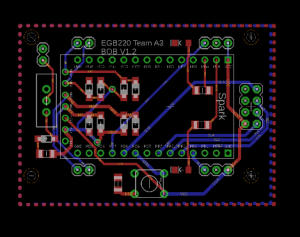
A ground poor layer was added to both sides of the PCB to ensure correct grounding and improve the ease with which the board could be routed. A routing size of 0.03 inches was used except for a few routes that ran between the pins of the Spark+ board. As all these routes will carry low voltage and current there was no technical concerns from using smaller traces. The board was designed to have as small a footprint as possible to reduce the overall cost. For this reason, surface mount components were used and, where possible, placed under the footprint of the Spark+ board. The only overhang of the BOB was to leave space for the external headers, a button and the two LED’s. Where possible 1206 size packages were used, however, some components, such as the diode, required a different package size due to their availability in Australia. All components of the PCB were ordered before finalising the design of the PCB.
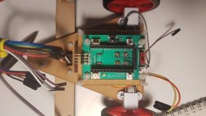
The final size of the board was 3.3635 square inches, only slightly larger than the Spark+ board. Headers for the sensor boards and motors were placed with consideration for the final mechanical design, on either side at the front and back of the BOB. This would ensure that they could be easily connected with minimal wire as the headers would already be near the physical placement of these components. 4 standoff holes were also added to ensure that it could be easily and securely mounted to the chassis.
Sensor Board
To be able to detect the centre white line and the edge markers a sensor array was required. The simplest way to detect different colours was using an IR emitter and sensor. By creating a voltage divider the changing voltage of the IR sensors can be recorded using the ADC pins of the Spark+ board. This data can then be analysed to determine the colour underneath the sensor.
To reduce costs and improve the accuracy of this process a combined package of IR emitter and collector were used, 6 QRD114 through hole IR emitter/detectors. These components are low cost and small, allowing compact PCB’s to be created. They also have a large operating range, allowing for more flexibility in chassis design. By considering the track which needed to be detected it was decided to place each of the line detecting sensors 9.6mm apart. This ensured that two sensors would be over the white line at all times, allowing extra computational checks to occur to ensure that the white line was being detected instead of a faulty reading or something on the track.
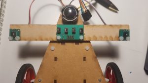
To reduce the cost of the sensor array it was split into three parts, four sensors in the middle to detect the white line and one sensor on each side of the robot to detect edge markers. Making the wing sensors modular allowed them to be easily fitted to any chassis and have their placement changed for better edge detection. The schematic for the three PCB’s was then created in Eagle. Similarly, to the BOB board a ground poor layer was added to each side of the boards as well as standoff holes for mounting.
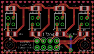
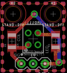
Although the wing sensors were initially designed to be placed in active mode, lighting inconsistencies would not allow accurate detection of different colours and hence the slow zone. These sensors were instead placed in switch mode as well and detection of the slow zone was solved programmatically. The final assembly of the sensor array is shown in.It was decided to place the central sensors in switch mode. This was done with great consideration for the computational requirements of the device. By designing them in switch mode either an analogue or digital read could be used to determine if they were detecting white or black. This could be used to improve computational time if required. Furthermore, it meant that no calibration code was required to be written to detect the centre line, as the same, or very similar voltage would be observed if there was some reflective surface underneath the central sensors.
